In the last couple of months we added support for the interactive modeling of architectural aspects in Sonargraph. Whilst our architecture DSL is tremendously powerful, there are situations where the new interactive modeling via the Architectural view is more appealing.
The Architectural view is is ideal for exploring architecture, designing architectural aspects and simulation of code refactorings on existing (even unfamiliar) code bases. Its power is derived from the unique combination of code exploration, architecture definition, simulation of code refactorings and visual feedback of architectural issues in real time.
For this blog post I chose FreeMind as example project, a freely available software written in Java offering a user interface based on Swing/AWT. The hypothetical task at hand is to see what needs to be done to implement another user interface based on let’s say SWT. The author of that popular free mind-mapping software probably never envisioned this requirement, but we have all seen frameworks come and go, so this is not a far-fetched requirement and is obviously not limited to SWT. I picked the software solely as an example to demonstrate how Sonargraph’s Architectural view helps to prepare the existing code base for such a task.
Approach
One approach to address the given task is to simply start implementing a SWT-based user interface using all existing classes without restrictions. This has the following negative consequences:
- SWT- and Swing/AWT-based code is intertwined leading probably to technical problems (e.g. due to different event queue implementations).
- If the product is deployed as different executables, each executable contains unnecessary code for the ‘inactive’ user interface.
- From an architectural perspective it would be a piece of software with unclear separation of responsibilities (SWT-based versus Swing/AWT-based code), higher coupling and worse maintainability.
A preferable approach would be to use the opportunity and think about an architectural division that avoids the above consequences. For this, the code base needs to be divided into distinct areas in order to clearly separate code for the different UI technologies. A natural initial division can look like this:
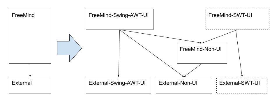
On the left-hand side you can see the current situation. All FreeMind code depends on External code provided by the Java Runtime.
We want to transform that into the right-hand side diagram. FreeMind and External code is now divided into UI and non-UI code. The 2 boxes with dashed borders (FreeMind-SWT-UI and External-SWT-UI) are needed once we start with the SWT user interface implementation.
In the following sections, I will describe, how Sonargraph’s Architectural view is used to design the target architecture. First, the core functionality of the Architectural view is explained, and then the design process step by step.
An Introduction to Sonargraph’s Architectural View
Sonargraph’s Architectural View is ideal for restructuring tasks and for architecture definitions. It offers a tree like view of the system showing nodes representing different elements (e.g. modules, packages, components and so forth) and their dependencies. Left-hand side arcs are downward and right-hand side arcs are upward dependencies as shown in the screenshot below. Upward dependencies are minimized giving a direct visual feedback of the system’s construction (i.e., which are the elements that rely the most on others). Nodes with child nodes can be expanded and collapsed. The collapse/expand figure (+/-) uses shades of grey as background color to visualize the number of children: The darker the background color of this figure more children it contains. Which children belong to the same expansion level is visually highlighted by boxes of different shades of blue.
An Architectural view can be created based on different structure modes. An initial exploration of the system quickly reveals, which mode is the most suitable:
- Physical With Root Directories – use this one if there is a good chance that the physical directory structure (including modules) has been used to group source files depending on how they should relate to each other.
- Physical Without Root Directories – use this one for the same reason as above but skipping root directories if they are not wanted.
- Logical Module Scope – use this one if the above does not apply and there is a chance that the logical package/namespace structure (including modules) has been used to group top-level types/functions and so forth on how they should relate to each other.
- Logical System Scope – use this one for the same reason as above but skipping modules if they are not wanted.
Note: The structure mode is chosen when the new Architectural view is created and cannot be changed later.
Additionally, the Architectural view offers 3 presentation modes that affect the display of recursive nodes. Those recursive nodes represent directories, packages or namespaces depending on the language (C++, C# or Java) and the structure mode used:
- Mixed – recursive nodes are compacted if they do not contain other non-recursive nodes (i.e., they are merged with their parent).
- Hierarchical – all recursive nodes are shown.
- Flat – only recursive nodes containing other non-recursive nodes are shown (i.e., only ‘leaf’ directories/packages/namespaces are shown).
Recursive node visualization: Technically there is no ‘contains’ relationship between directories, packages or namespaces, for example take the 2 packages in Java com.foo and com.foo.bar. For the compiler, they are distinct as com.xxx and com.yyy but in Mixed and Hierarchical presentation modes parent and child relations are visually used. A lot of developers use that semantic in projects to ease navigation and express logical containment.
The initial Architectural view of FreeMind without any architectural artifacts using structure mode Physical Without Root Directories and presentation mode Mixed looks like this:
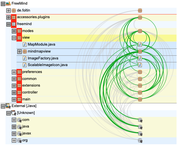
Some additional visual elements are eye-catching that help to interpret the dependencies between nodes. Horizontal grey lines act as level separators. The packages de.foltin, accessories.plugins and freemind (the direct children of module FreeMind) are on the same level. Nodes on the same level are either not using each other or belong to the same cycle in relation to the parent node taking into account all dependencies of the given element itself and all its child nodes (note: depending on the chosen presentation mode the nodes marked as cyclic might differ, since the child nodes’ dependencies are taken into account). In the above example accessories.plugins and freemind form a cycle and they are marked with rectangles using shades of red. Since this 2 packages are on the same level as de.fotlin (the cyclic elements do not use de.fotlin) another separator (a red horizontal line) is added to visually separate cyclic from non-cyclic nodes. All direct package children of the freemind package form a cycle. Selected nodes have a yellow and all connected nodes a lighter yellow (ocher) background. External elements (i.e., elements that are not part of the analyzed system, but are referenced) are marked with an ‘e’.
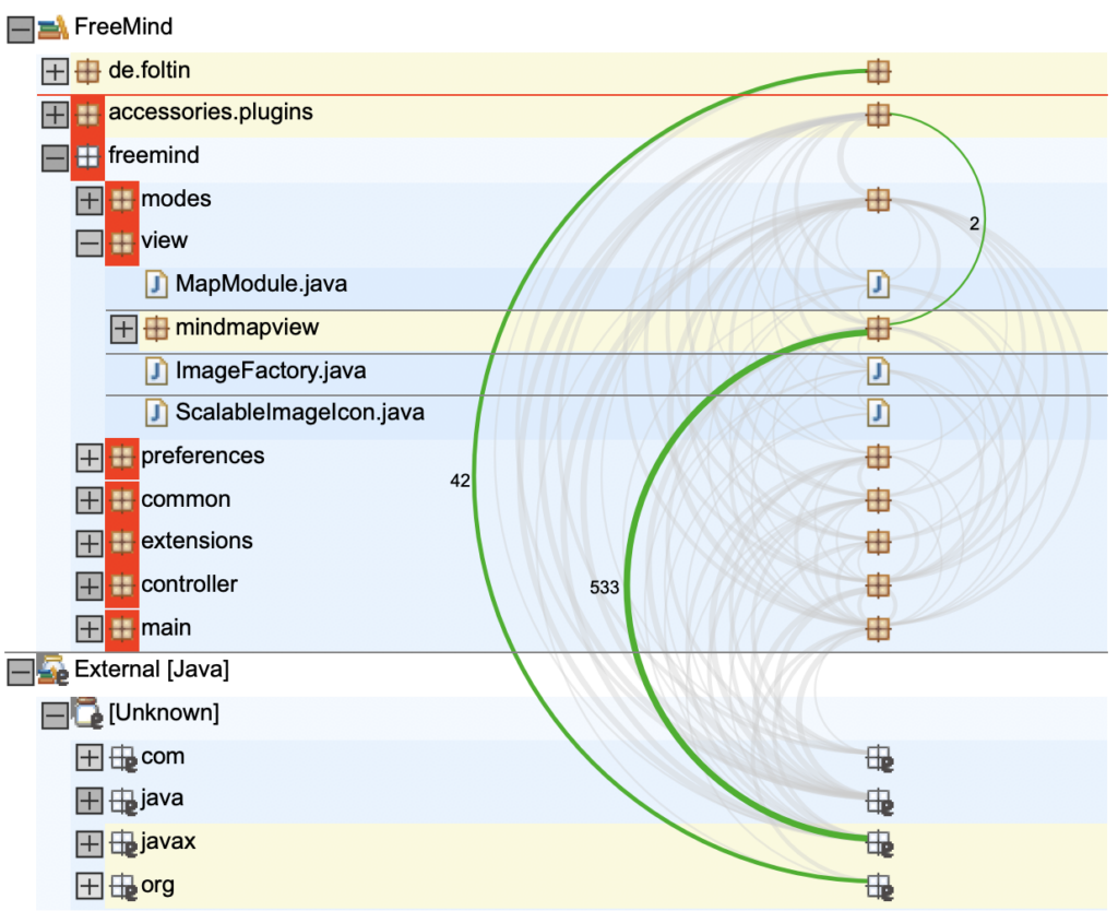
When selecting dependencies their weight (i.e., number of underlying parser dependencies) is shown as a small number attached to the arc. Also, all connected nodes get a lighter yellow (ocher) background. That looks like this:
The sheer number of nodes and dependencies can be overwhelming. Therefore, the Architectural view offers a powerful Focus concept. Selected nodes and/or dependencies can either be removed from the tree (an operation without any options) or they can be focused offering a lot of options. The following dialog shows all options (note: not all options are always shown – that depends on the context):
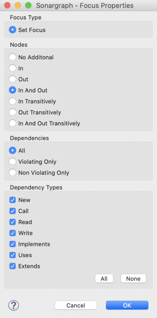
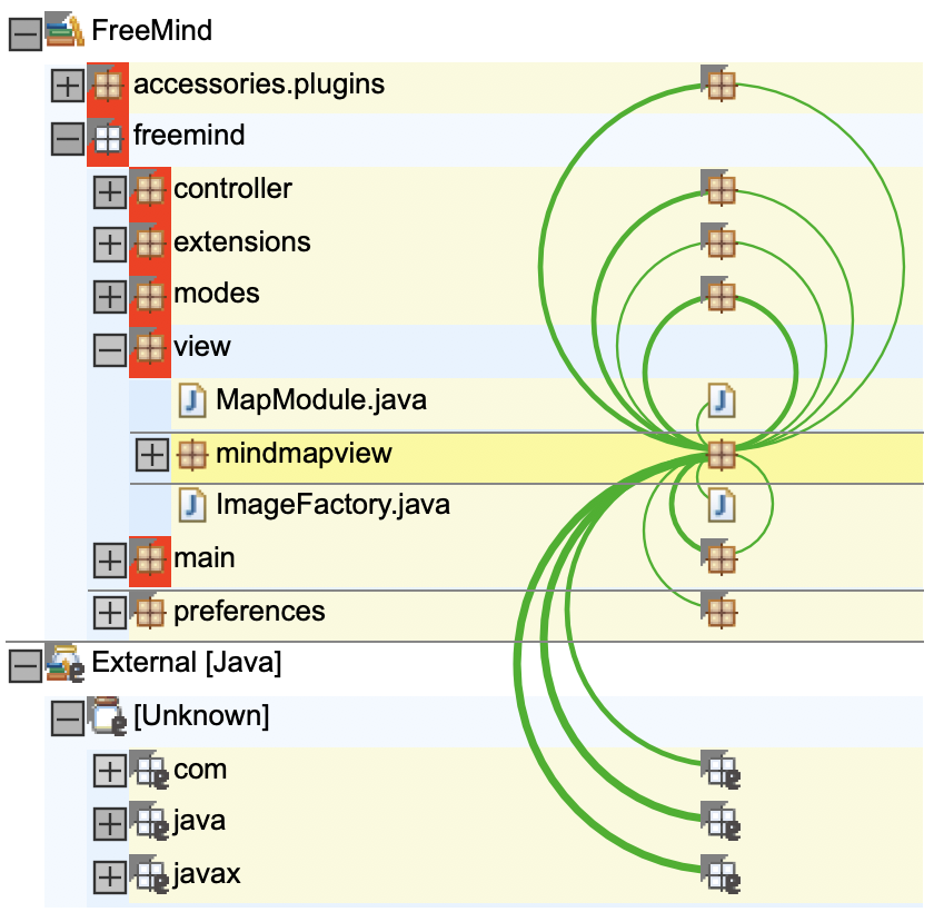
By using a focus you can dramatically reduce the number of visible nodes and ‘focus’ on what you need to see. The focus is completely dynamic and nodes can consecutively be removed or more nodes can be added. Currently invisible nodes (i.e., nodes removed by focus operations) can be searched (use CMD+F on Mac or Ctrl+F on Windows and Linux to bring up the Search dialog) an re-added with another focus operation. When not all children of a given node are shown (due to a focus), the node is decorated with a small grey triangle. The same applies to a dependency. If not all contained parser dependencies are shown it is visually marked with a grey triangle (i.e., only partially shown). The following tree displays partially shown nodes. The package mindmapview was focused with the option Nodes: In and out and all dependency types checked only to illustrate how this looks like:
In order to work with Architectural views you need to first setup a system with Sonargraph and successfully parse/analyze it. You can find the corresponding information in the user manual. Once you have your system setup you can create as many Architectural views as you want. An Architectural view acts as a kind of sandbox for applying refactorings without modifying the code base. All refactorings or architecture related operations are stored in a corresponding file. More information about the creation and features of Architectural views will become clear in the following sections and details can be found in the corresponding chapters of the user manual.
Define an Architecture Aspect
After a first introduction of the Architectural view, I now want to demonstrate how it can be used for defining the target architecture. As a reminder, the goal is to have a clear separation of UI-related and UI-independent code, so it is easy to see, which parts can be re-used for the implementation of another UI.
As a first step, I created a Sonargraph system for FreeMind only based on the compiled Java class files contained in a single module. After parsing the system I created an Architectural view with structure mode Physical Without Root Directories using the default presentation mode Mixed. The following screenshot shows the initial content:
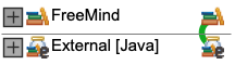
The view now represents the left-hand side of our initial diagram. The nodes FreeMind (module) and External are separated by a level separator because FreeMind is one level above the External node (i.e., FreeMind uses External).
Now, we want to create an artifact that represents the Swing/AWT-dependent code in FreeMind. First, I search for the AWT code using the Search dialog (context menu without selection choosing Find Elements… or CMD+F/Ctrl+F):
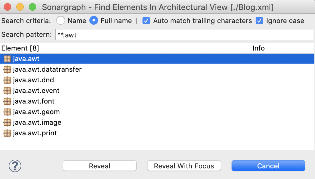
With selected package java.awt I use Reveal With Focus with option Nodes: No additional and all dependency types. I do the same with package javax.swing but choosing Focus Type: Add To Focus which is now possible because we already have a focus. That will leave only the two nodes of interest in our tree.
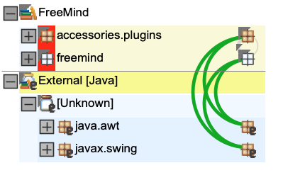
Then, I can focus on java.awt and javax.swing with Nodes: In Transitively as shown in the next screenshot:
The resulting tree now only contains Swing/AWT related external and internal elements and the grey decorators highlight that elements have been filtered:
Details about the filtering caused by the focus operation are given in the Properties view as depicted below:

The Applied Focus provides the information that most of the internal code (~92%) depends somehow on the Swing/AWT user interface technology. This makes our hypothetical task of providing another user interface surely not easier. Our hope is that some code that is not user interface related got tangled up by accident.
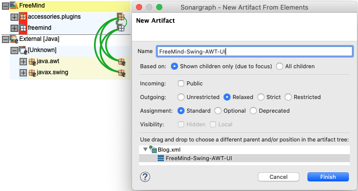
Let us move on and assign all Swing/AWT related code to the corresponding two artifacts from our diagram, FreeMind-Swing-AWT-UI and External-Swing-AWT-UI. The artifact creation dialog is offering 2 modes for the assignment: Shown children only (due to focus) and All children. Since we only want to assign the elements depending on the user interface technology (the ones that are visible) we need to use the first option.
About the assignment of nodes to artifacts: It is extremely helpful being able to choose between the visible nodes (Shown children only (due to focus)) and all nodes (All Children). The focus operations help you to get exactly the nodes you want, even if they are distributed over a lot of different recursive nodes (directories, packages, namespaces). Additionally the presentation mode can help to achieve your goal. When assigning recursive nodes in Flat mode only the direct non-recursive node children are used for assignment. The architectural view offers also assignment based on pattern matching and other useful criteria. This might be helpful in case physical or logical containment is not very instructive. This is explained in Sonargraph’s user manual.
First, I select the FreeMind module and via the context menu entry New Artifact From Elements… Then, I create the artifact FreeMind-Swing-AWT-UI. The selected option Outgoing: Relaxed means that it may use all (future) artifacts underneath itself. Thus, the order of the artifacts has meaning!
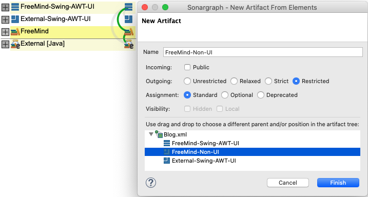
Then I select External [Java] and create the artifact External-Swing-AWT-UI the same way with the same options. To finish this step I clear the focus by selecting Clear Focus in the context menu to make all elements visible again. The next step is to create the internal artifact FreeMind-Non-UI from the diagram. I select the FreeMind module node and bring up the “New Artifact” dialog via the context menu as before. I select the option Outgoing: Restricted because I do not want this artifact to use External-Swing-AWT-UI. The position of artifacts is modifiable by drag and drop in the creation dialog show in the following screenshot:
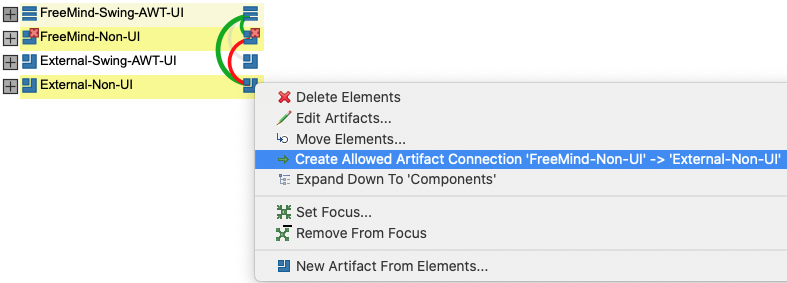
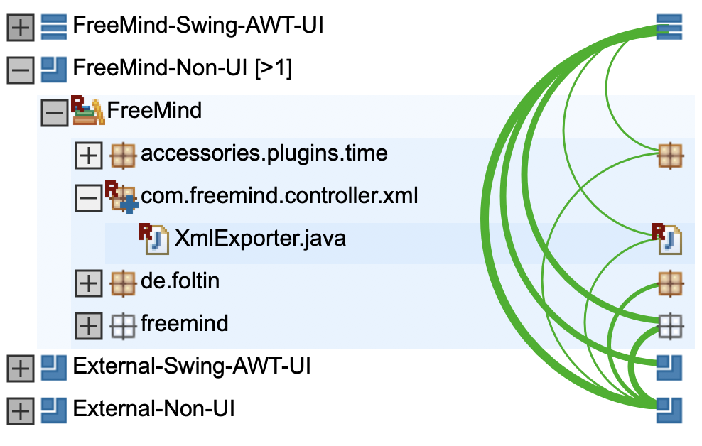
I also create an artifact for the non-Swing/AWT related External [Java] node and 2 empty artifacts for the SWT based implementation. This leads to our four artifacts from the diagram. As seen in the next screenshot there is 1 red arc meaning that all parser dependencies from FreeMind-Non-UI to External-Non-UI are architecture violations. This is caused by the option Outgoing: Restricted when the artifact FreeMind-Non-UI was created. Obviously, these dependencies must be allowed and this can be done by selecting the two artifacts and bring up the context menu selecting Create Allowed Artifact Connection ‘FreeMind-Non-UI’ -> ‘External-Non-UI’ (note: the order in which the 2 artifact nodes are selected is important, it determines the direction of a possible allowed connection creation):
Now we have a first architecture aspect without any violations. The reason I call it an ‘aspect’ is because it is possible (and an advisable approach) to create several aspects that all together would contribute to the the system’s overall architecture.
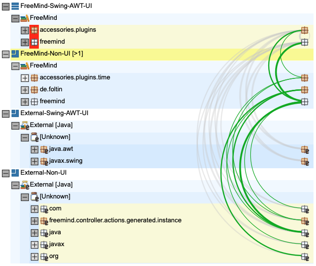
The name addition [>1] of FreeMind-Non-UI means that there is 1 allowed outgoing dependency. The concrete allowed target artifacts show up in the Properties view.
Define Refactorings
Let us assume we have introduced our first SWT-based code and want to reuse the already existing source XMLExporter.java. Currently, it is located in the artifact FreeMind-Swing- AWT-UI. Our architecture check would complain when using that artifact from our FreeMind-SWT-UI artifact. So, this source is our first refactoring candidate! To reuse XMLExporter, it must be contained in the artifact FreeMind-Non-UI.
Since we also want to improve our package naming policy we create a new package called com.freemind.controller.xml underneath the FreeMind module in the target artifact FreeMind-Non-UI via the context menu entry New Element… on the selected FreeMind module. After that we simply move our source with drag and drop into the new package leading to the following tree:
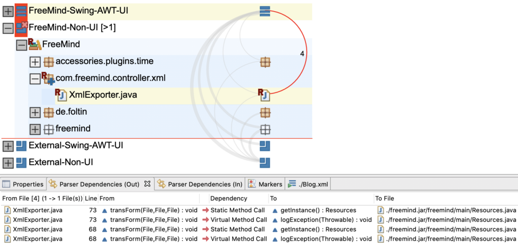
The new package com.freemind.controller.xml is marked with a blue ‘+’ indicating that this is a new package. We can also see that we now have an architecture violation (which I selected) consisting of 4 parser dependencies shown in detail in the Parser Dependencies (Out) view. I would say that there is no need to log exceptions in a centralized class (Resources.java), tying together UI and non-UI code as a result. I would recommend using a common logging framework for that purpose or at least extracting the logging code into a class also contained in the FreeMind-Non-UI artifact. So, I create a delete refactoring for this dependency via the context menu entry Delete Dependency on the selected upward dependency. Nodes affected by a refactoring are marked with an ‘R’:
Transfer the Architecture Aspect and the Refactorings
Once we are done with our architecture aspect and the required refactorings we can simply choose to transfer our work into ‘production’. The transfer wizard is opened by selecting the context menu entry Transfer… without any selection in the Architectural view. There you can review some details before creating a new Architecture DSL file containing the architecture aspect. The refactorings are added to the currently active modifiable virtual model. If you are not familiar with our Architecture DSL and/or virtual models, please consult the user manual.
Note: In order to be able to transfer the defined refactorings a modifiable model must be currently active. The Parser model is not modifiable, as it represents the current system as parsed from disk.
The usage of the term ‘production’ explained: Refactorings that are contained in the active modifiable model are shown as tasks in our Standalone product and the IDE integrations. They alter the structure and probably associated metrics. Active architecture aspects can potentially create architecture violations which also show up in our Standalone product and the IDE integrations. Also they alter some architecture related metrics and they might even break the build when configured accordingly. So, it is really important in a project to agree on the used active modifiable model containing refactoring-, ignore- and other task definitions as well as the set of active architecture aspects.
Conclusion
In this blog article, I have demonstrated the advanced functionalities of Sonargraph’s Architectural view for code exploration and defining an architecture at the same time. Where the code does not match the design, refactorings can be simulated and their effects investigated before the code is modified. This immediate feedback makes the Architectural view a big time-saver and fun to work with. The implementation of the Architectural view was inspired by Carola Lilienthal’s book Sustainable Software Architecture. If you want to give it a spin, request an evaluation license on our web site.
Hi,
I am interested to try the tool.
so I am trying to follow what you did in https://blog.hello2morrow.com/2020/06/design-architecture-improvements-using-sonargraphs-architectural-view/
I have cloned the FreeMind to a directory
Then created a new system .
Then created a new Java module.
Then I try to menu “Manage Java Source/Class Root Directories/Archives…” and Detect …
But Not sure what files to selects from the FreeMind dirc. ??
When ever I select a file it gives “At Least One Java Class Root Directory Needed.” msg.
Hi,
Thank you for your interest.
I didn’t use source files for the analysis. I used the .class files contained in the freemind.jar in the installer download (for Mac).
Sonargraph must at least have the .class files to be able to analyze a system, therefore the message “At Least One Java Class Root Directory Needed.”.
Information about that can be found here: http://eclipse.hello2morrow.com/doc/standalone/content/create_module_java_manually.html
If also the source files are used (additionally/optional -> but recommended) then you obtain more information from the analysis and obviously can have a look at the source code.
I hope that helps.
If you have more questions or need further assistance feel free to contact me again.
Regards